


A Spring Design Slide Rule
Originally published in the Proceedings of the 14th International Meeting of Slide Rule Collectors
Originally published in the Proceedings of the 14th International Meeting of Slide Rule Collectors
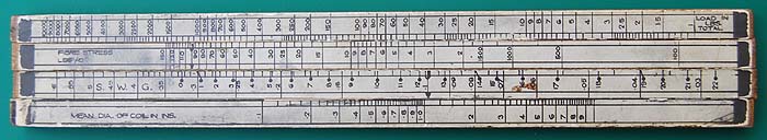
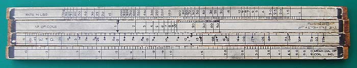
Figure 1. Spring design slide rule, side 1
Figure 2. Spring design slide rule, side 2
Size: 295 x 45 x 10 mm
The illustrations show both sides of an unusual slide rule for designing coil springs. On each side there are two slides. The rule is made of three layers of 3-ply plywood with paper scales glued on.
Let us assume that we wish to design a coil spring given the required spring rate, the maximum load and the mean diameter of the coil. On side 1 set the number of coils (choose a number) on the upper slide against the spring rate (in lbs/inch) on the stator. Set the arrow on the lower side against the mean diameter. Read the wire gauge on the lower slide against the arrow on the upper slide.
We now have to check that the stress in the wire is not excessive. On side 2 set the arrow on the lower slide against the mean diameter. Next set the arrow on the upper slide against the wire gauge on the lower slide. The fibre stress (shear stress) can now be read on the upper slide against the maximum load on the upper stator.
I performed a couple of checks on the results of a calculation for a spring one inch in diameter, made of 0.1 inch diameter steel wire with ten turns and a maximum load of 20 lb.
The formula for the shear stress in a close coiled helical spring is: τ = 16.W.R/л.d³
where W = load, R = mean coil radius, and d = wire diameter.
For a 20lb load, 1in coil diameter and 0.1in wire diameter this gives a shear stress of 50,930 psi compared with a slide rule figure of 50,000, i.e. within the accuracy of reading the slide rule.
For the spring rate I used a table in Kempe’s Engineers Year Book. For the above spring this gave a rate of 17.5 lb/in, whereas the rule gave 16 lb/in, a difference of about 10%.
The illustrations show both sides of an unusual slide rule for designing coil springs. On each side there are two slides. The rule is made of three layers of 3-
Let us assume that we wish to design a coil spring given the required spring rate, the maximum load and the mean diameter of the coil. On side 1 set the number of coils (choose a number) on the upper slide against the spring rate (in lbs/inch) on the stator. Set the arrow on the lower side against the mean diameter. Read the wire gauge on the lower slide against the arrow on the upper slide.
We now have to check that the stress in the wire is not excessive. On side 2 set the arrow on the lower slide against the mean diameter. Next set the arrow on the upper slide against the wire gauge on the lower slide. The fibre stress (shear stress) can now be read on the upper slide against the maximum load on the upper stator.
I performed a couple of checks on the results of a calculation for a spring one inch in diameter, made of 0.1 inch diameter steel wire with ten turns and a maximum load of 20 lb.
The formula for the shear stress in a close coiled helical spring is: τ = 16.W.R/л.d³
where W = load, R = mean coil radius, and d = wire diameter.
For a 20lb load, 1in coil diameter and 0.1in wire diameter this gives a shear stress of 50,930 psi compared with a slide rule figure of 50,000, i.e. within the accuracy of reading the slide rule.
For the spring rate I used a table in Kempe’s Engineers Year Book. For the above spring this gave a rate of 17.5 lb/in, whereas the rule gave 16 lb/in, a difference of about 10%.