

Originally published in the Slide Rule Gazette, Issue 12, Autumn 2011
In the late nineteenth and early twentieth centuries factory machinery was generally driven via line shafting from one or more stationary steam, gas or oil engines rather than by individual electric motors. Whilst each machine was generally driven by a wide, flat, leather belt and a fast and loose pulley arrangement on the line shaft, the line shafts themselves would often be driven by a series of cotton ropes from pulleys or the fly-wheels of the engine.
One of the principle suppliers of cotton driving ropes was Thomas Hart of the Lambeth Rope Works, Blackburn, England. Lancashire was at that time the centre of the cotton industry in Britain. This horse power calculator was given to customers by Thomas Hart.
One of the principle suppliers of cotton driving ropes was Thomas Hart of the Lambeth Rope Works, Blackburn, England. Lancashire was at that time the centre of the cotton industry in Britain. This horse power calculator was given to customers by Thomas Hart.
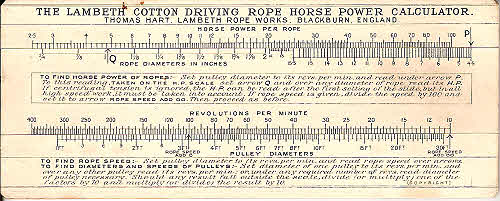
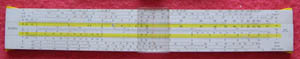
Fig. 1, The upper side of the Lambeth Cotton Driving Rope Horse Power Calculator
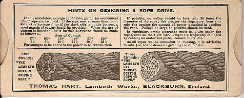
Fig. 2, The reverse.
The calculator is illustrated in figures 1 and 2. It was given away in a brown paper envelope having ‘With Thomas Hart’s Compliments’ printed in red starting in the tope left hand corner.
The calculator itself is a simple affair, made of stout card with a single slide. The upper scale is for Horse Power per Rope, the next for Rope Diameters in Inches. The third is for Revolutions per Minute and the last for Pulley Diameters. The instructions for its use are printed in the centre of the slide and below the bottom scale. These read as follows:
To find horse power of ropes:- Set pulley diameter to the revs per min and read under arrow P. to this reading, taken on the H P scale set arrow Q and over any diameter of rope read its H P. If centrifugal tension is ignored the H P can be read after the first setting of the slide, but in all high speed work, it must be taken into account. If rope speed is given, divide the speed by 100 and set it to arrow Rope Speed add 00. Then proceed as before.
To find rope speed:- Set pulley diameter to its revs per min and read rope speed over arrows.
To find diameters and speeds of pulleys:- Set diameter of one pulley to its revs per min. and over any other pulley read its revs per min.; or under any required number of revs read diameter of pulley necessary. Should any results fall outside the scale, divide (or multiply) one of the factors by 10 and multiply (or divide) the result by 10.
The reverse has illustrations of both the three and four strand driving ropes. These illustrations featured in many of their adverts of the years. It also has ‘Hints on Designing a Rope Drive’. These include extra allowances to be made for steeply inclined ropes and ropes in less than 180 degree contact with the driving pulley.
The subject of cotton rope drives1 2 was dealt with in some detail in two of the Fowler pocket books that were issued every year by the Scientific Publishing Co., Manchester. They were also dealt with in each issue of Kempe’s Engineer’s Year Book.
In Fowler’s Mechanical Engineer’s Pocket Book for 1948 the following formulae are given:
Horse power = (T1 - T 2) S / 33,000
Where T1 = total tension on tight side in pounds
T2 = total tension on slack side in pounds
S = speed in feet per minute
Stress due to Centrifugal Force = w v2 / g
Where w = weight of a foot length of rope in pounds
v = velocity in feet per second
g = acceleration due to gravity = 32
There is also a table of Power Transmitted (centrifugal tension taken into account) for a range of speeds and rope diameters.
As an example this gives transmitted horse power of 29.0 for a rope diameter of 1 3/8 inches and a speed of 4500 feet per min.
Using the calculator:
1. The calculator starts from pulley diameter and revs per min so assume a pulley diameter at least 30 times the rope diameter, say 60 inches, then the revs per min for a rope speed of 4500 feet per min will be 4500 / 5π = 286 rpm. The assumed diameter has no effect on the subsequent calculation.
2. On the lower scales set 286 rpm against 5 ft
3. Read under P = 15.4
4. Set arrow Q to 15.4 on HP scale
5. Against 1 3/8 rope diameter read HP = 29.0 which agrees with the table.
Thomas Hart were evidently one of the leading makers of cotton driving ropes and advertised regularly in a number of annual publications and other texts. For instance their adverts appeared in most editions of C N Pickworth’s ‘The Slide Rule’ from 1901 to 1920, as well as many editions of Fowler’s Mechanical Engineer’s Pocket Book and Kempe’s Engineer’s Year Books. Figure 3 is a copy of the advert in the 1932 edition of Kempe’s Engineer’s Year Book.
The calculator itself is a simple affair, made of stout card with a single slide. The upper scale is for Horse Power per Rope, the next for Rope Diameters in Inches. The third is for Revolutions per Minute and the last for Pulley Diameters. The instructions for its use are printed in the centre of the slide and below the bottom scale. These read as follows:
To find horse power of ropes:-
To find rope speed:-
To find diameters and speeds of pulleys:-
The reverse has illustrations of both the three and four strand driving ropes. These illustrations featured in many of their adverts of the years. It also has ‘Hints on Designing a Rope Drive’. These include extra allowances to be made for steeply inclined ropes and ropes in less than 180 degree contact with the driving pulley.
The subject of cotton rope drives1 2 was dealt with in some detail in two of the Fowler pocket books that were issued every year by the Scientific Publishing Co., Manchester. They were also dealt with in each issue of Kempe’s Engineer’s Year Book.
In Fowler’s Mechanical Engineer’s Pocket Book for 1948 the following formulae are given:
Horse power = (T1 -
Where T1 = total tension on tight side in pounds
T2 = total tension on slack side in pounds
S = speed in feet per minute
Stress due to Centrifugal Force = w v2 / g
Where w = weight of a foot length of rope in pounds
v = velocity in feet per second
g = acceleration due to gravity = 32
There is also a table of Power Transmitted (centrifugal tension taken into account) for a range of speeds and rope diameters.
As an example this gives transmitted horse power of 29.0 for a rope diameter of 1 3/8 inches and a speed of 4500 feet per min.
Using the calculator:
1. The calculator starts from pulley diameter and revs per min so assume a pulley diameter at least 30 times the rope diameter, say 60 inches, then the revs per min for a rope speed of 4500 feet per min will be 4500 / 5π = 286 rpm. The assumed diameter has no effect on the subsequent calculation.
2. On the lower scales set 286 rpm against 5 ft
3. Read under P = 15.4
4. Set arrow Q to 15.4 on HP scale
5. Against 1 3/8 rope diameter read HP = 29.0 which agrees with the table.
Thomas Hart were evidently one of the leading makers of cotton driving ropes and advertised regularly in a number of annual publications and other texts. For instance their adverts appeared in most editions of C N Pickworth’s ‘The Slide Rule’ from 1901 to 1920, as well as many editions of Fowler’s Mechanical Engineer’s Pocket Book and Kempe’s Engineer’s Year Books. Figure 3 is a copy of the advert in the 1932 edition of Kempe’s Engineer’s Year Book.
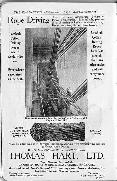
Fig. 3 Thomas Hart advert showing rope drives in a cotton spinning mill driven by an engine of 1750 indicated HP.
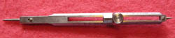
Having just received the Lambeth calculator another related item also appeared on ebay that I was fortunate to obtain. This, shown in figure 4, is a rope gauge for cotton driving ropes made by John Rabone and Sons of Birmingham. Rope gauges were a stock item from Rabone but these had tables on them for manila, sisal and steel ropes.
This one, however, was a special made for Scar Top Ropery, Burnley, Lancs., the maker of the ‘Cooper’ cotton driving rope.
This one, however, was a special made for Scar Top Ropery, Burnley, Lancs., the maker of the ‘Cooper’ cotton driving rope.
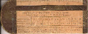
It has a simple table of rope diameter versus horse power per rope. This gives a HP of 28 for a 1 3/8 inch diameter rope. The note says that these are the highest powers advisable for speeds of 4000 to 5000 feet per min. and a minimum pulley diameter of 32 times the rope diameter.
The calliper slide is calibrated for inches circumference on the upper face and diameter on the under side.
It has been interesting researching this now almost forgotten, but once commonplace, way of driving machinery in cotton mills and other factories. The calculator has been shown to give an accurate result for the maximum power that can be efficiently and safely transmitted by a cotton driving rope, as an alternative to using tables in one of the engineer’s year books.
1 Fowler’s Mechanics’ and Machinists’ Pocket Book and Diary
2 Fowler’s Mechanical Engineer’s Pocket Book
| Early Sets |
| Traditional Sets |
| Later Sets |
| Major Makers |
| Instruments |
| Miscellanea |
| W F Stanley |
| A G Thornton |
| W H Harling |
| Elliott Bros |
| J Halden |
| Riefler |
| E O Richter |
| Kern, Aarau |
| Keuffel & Esser |
| Compasses |
| Pocket compasses |
| Beam compasses |
| Dividers |
| Proportional dividers |
| Pens |
| Pencils |
| Rules |
| Protractors |
| Squares |
| Parallels |
| Pantographs |
| Sectors |
| Planimeters |
| Map Measurers |
| Miscellaneous |
| Materials Used |
| Who made them |
| Who made these |
| Addiator |
| Addimult |
| Other German |
| USA |
| Miscellaneous |
| Microscopes |
| Barometers |
| Hydrometers & Scales |
| Pedometers |
| Surveying Instruments |
| Other instruments |
| Workshop Measuring Tools |
| Catalogues & Brochures |
| Micrometers & Verniers |
| Engineering rules and gauges |
| Wood rules & calipers |
| Dial gauges & miscellaneous |