

A Simple Electric Illuminant for Magic Lanterns
Earlier in 2016 my wife asked me to take her to view the toy and collectables sale at our local auction house. We didn’t think much of the toys for sale but did notice a collection of magic lanterns and slides. The best of three magic lanterns was a Russian iron one, the estimate seemed quite reasonable, and I was tempted to place a commission bid. I won it and then started to think about what I could do with it.
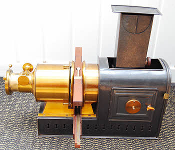
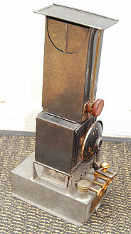
As you will see from the pictures it was fitted with an improved Stock-Wrench patent oil lamp. Indeed I bought it because it still had its original lamp and had not been converted.
However I realised that, if I could design and make a simple electric illuminant that could be placed inside the lamp housing without in any way modifying the lantern itself then I could use it to give magic lantern shows. My requirements were:
However I realised that, if I could design and make a simple electric illuminant that could be placed inside the lamp housing without in any way modifying the lantern itself then I could use it to give magic lantern shows. My requirements were:
it must be easily installed in the lamp housing
it should at least equal the power of the oil lamp
it should provide even illumination
it should not generate excessive heat
it should be safe
it should be cheap and easy to construct
The first task was to measure up the lamp housing to determine the space available and where the centre of the light source should be. For the latter I assumed that it would need to be on the centre-line of the optical system and where the centre of the four wicks of the lamp would lie. However I also decided that this would need to be adjustable to suit the beam angle of any lamp used.
After some thought I decided that a light source with built in reflector would be best and that this would need to be easily mounted with its axis horizontal. In this lantern the lamp housing is approximately 17.5 cm long, 11.5 cm wide and 21 cm high with rounded upper corners. The condenser is about 10 cm diameter.
Now it so happens that GU10 spotlight bulbs used in down-lighters are compact and easily mounted using the standard down-lighter fitting with one simple modification required. However the halogen bulbs sold with these fittings emit too much heat for use in a confined space. Fortunately there are now replacement LED bulbs that give the same light output at one tenth the current. They come in both spotlight and wide beam configurations and the spotlight version is the one to use. It has the same 36 degree beam angle as the halogen variety and a simple calculation will show that with the bulb face at the same distance as the centre of the oil lamp light it should (and does) evenly illuminate the condenser. The LED bulb I used is rated at 5 watts and gives 340 lumens compared to the 300 lumens output of a 40 watt (50 watt equivalent) halogen GU10. It also has the benefit of a more even field of illumination.
After some thought I decided that a light source with built in reflector would be best and that this would need to be easily mounted with its axis horizontal. In this lantern the lamp housing is approximately 17.5 cm long, 11.5 cm wide and 21 cm high with rounded upper corners. The condenser is about 10 cm diameter.
Now it so happens that GU10 spotlight bulbs used in down-
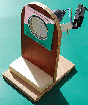
The mount consists of three parts screwed together: a 12mm plywood base, a 12mm plywood vertical, and a block of 2 x 1 to hold them in alignment. A hole, centred at the height of the optical axis, and the diameter of the down-lighter needs to be cut in the vertical member and I used a fret-saw for this. I used a down-lighter with tilt-able lamp housing for final adjustment but this proved unnecessary.
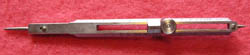
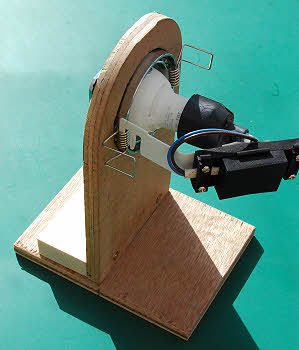
I did mention that a small modification would be necessary. The spring wire extensions that hold the fitting in place would protrude too far to enable the assembly to be placed inside the lamp housing so I bent these at mid-point in a right-angle. This does make inserting the down-lighter into the hole a trifle difficult and I suggest you tie them together first and then release them once through the hole. The next picture shows the reverse of the assembly.
I did mention that a small modification would be necessary. The spring wire extensions that hold the fitting in place would protrude too far to enable the assembly to be placed inside the lamp housing so I bent these at mid-
This clearly shows the bent spring extensions and also the electrical connections. The bulb is inserted from the front and held in place by a spring clip and is electrically connected by the push-on bayonet fitting at the rear that is supplied with the down-lighter, as is the electrical connection box and its mounting. The top of the connection box is unclipped to reveal the connections inside to which a power lead needs to be connected, ensuring also that the outer cable is clamped. This is all explained in the instructions that come with the unit.
Note that the ply-wood base I have made is about 2.5 cm shorter, at the front, than the space in the lamp housing. This allows for fore and aft movement to get the optimum lamp position. Also the cable connecting block does protrude from the back of the housing and I cannot completely close the lamp housing rear door. Whilst the electrical parts are, in the unit I’ve used, double insulated I would advise the following safety precautions:
Note that the ply-
Carefully inspect the unit for any damage or loose connections before use
Use an RCD
When adjusting lamp position, either hold the wooden base or, preferably, disconnect from the supply.
Keep the metal parts of the down-lighter out of contact with the lantern lamp housing.
Could my lantern be used as a scientific lantern with this illuminant?
Optical Projection by Wright is an excellent reference for scientific demonstration using the magic lantern, written originally in 1890. I have the fourth edition of 1906 updated by his son after his father’s death in a railway accident at Saltford, Somerset on December 16th, 1905.
I have tried some simple experimentation and the conclusion I have come to is that it is not really suitable. If you remove the front lens unit from the lantern and switch it on you will observe a projected image of the LED array and by adjusting the position of the lamp unit you can bring this to a sharp focus or merge the light. With the light merged it can be used for shadow projection but significantly fainter secondary images are present so it is certainly not ideal and emphasises the fact that an LED array is not a point source.
If you place a slit in front of the nozzle then multiple images of it are projected. Replace the front lens unit and place the slit in the place for the slide carrier and it can be brought into focus as a sharp, single image by the usual focussing arrangement (in this case a combination of sliding tube and rack and pinion) so it is clear that it is the front lens that actually combines multiple beams from the condenser into one. It might be that a further condensing lens might also achieve that result but I have not tried that.
As an aside, when focussing the LED array with the front lens unit removed chromatic aberration can be observed.
I also tried to use it for microscope projection. There is clearly not enough power for high magnifications and I experimented with a small, pocket microscope. I could not get a clear image, again showing the need for a point source. It is possible that a further condensing lens would improve this.
A conventional halogen GU10 bulb would be much closer to a point source and could be used in the same assembly. However you effectively have a 5W lamp and a 35W heater in that situation and these bulbs are intended to be mounted much further from any obstruction than the 50mm or so from the condenser and so, besides making the housing very hot (OK for a wood bodied lantern with no exposed metal to touch), it is likely the reflected heat will cause the bulb to fail prematurely.
1. Optical Projection, A Treatise on the Use of the Lantern in Exhibition and Scientific Demonstration, Lewis Wright, 4th edition, revised by Russell S Wright, Longmans Green and Co, 1906
| Early Sets |
| Traditional Sets |
| Later Sets |
| Major Makers |
| Instruments |
| Miscellanea |
| W F Stanley |
| A G Thornton |
| W H Harling |
| Elliott Bros |
| J Halden |
| Riefler |
| E O Richter |
| Kern, Aarau |
| Keuffel & Esser |
| Compasses |
| Pocket compasses |
| Beam compasses |
| Dividers |
| Proportional dividers |
| Pens |
| Pencils |
| Rules |
| Protractors |
| Squares |
| Parallels |
| Pantographs |
| Sectors |
| Planimeters |
| Map Measurers |
| Miscellaneous |
| Materials Used |
| Who made them |
| Who made these |
| Addiator |
| Addimult |
| Other German |
| USA |
| Miscellaneous |
| Microscopes |
| Barometers |
| Hydrometers & Scales |
| Pedometers |
| Surveying Instruments |
| Other instruments |
| Workshop Measuring Tools |
| Catalogues & Brochures |
| Micrometers & Verniers |
| Engineering rules and gauges |
| Wood rules & calipers |
| Dial gauges & miscellaneous |