

The first thirteen slide charts and calculators on this page were generously donated to me by David Shore, who also provided links to Wikipedia pages to help me understand them as my electronics knowledge is rather limited. I apologise now for any errors I may have made in the descriptions.
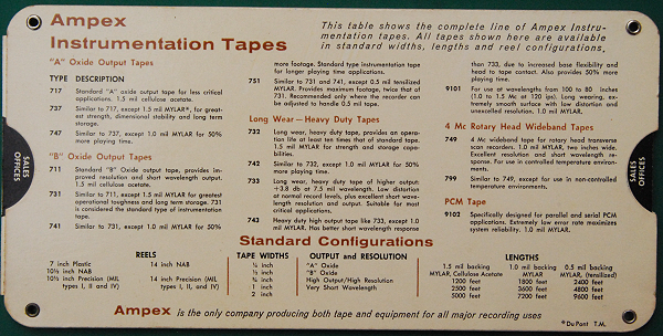
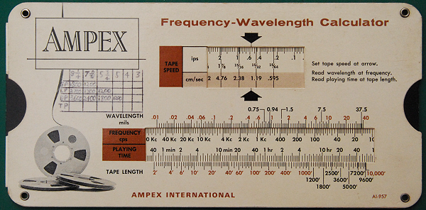
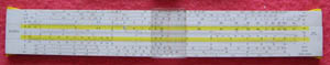
Ampex International AI.947 Frequency Wavelength Calculator made by Perrygraf, dated 1963. Setiing the tape speed in the upper window enables the wavelength to be read against frequency and the playing time against tape length. There is a small handwritten table under the brand name. The reverse gives details of Ampex instrumentation tapes and the standard configurations for them.
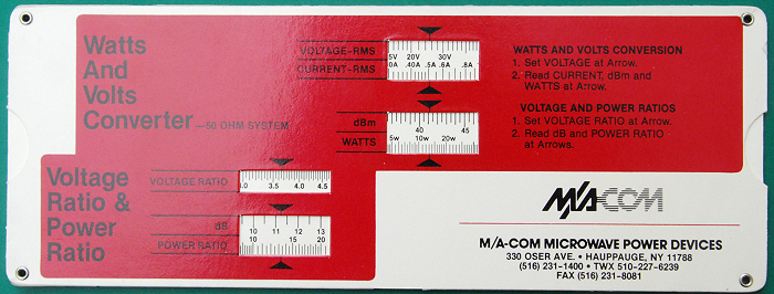
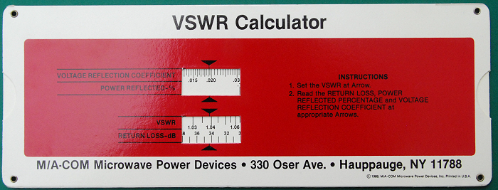
M/A.COM Microwave Power Devices VSWR Calculator ©1989 made by the American Slide Chart Corporation. The Voltage Standing Wave Ratio (VSWR) in radio and telecommunications engineering is a measure of the impedance matching of loads to the characteristic impedance of a transmission line or waveguide (ref. Wikipedia)). It is particularly relevant to the matching of radio transmitters and receivers to their antennae. On the upper side, setting the VSWR to the arrow enables reading the return loss, power reflected percentage and voltage reflection coefficient. On the other side there is a Watts and Volts Converter for a 50 ohm system, and a Voltage Ratio to Power Ratio converter.
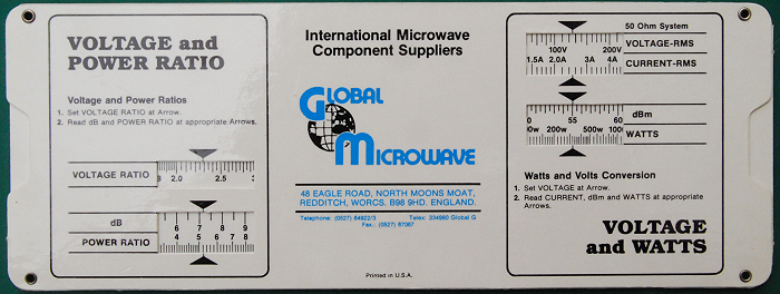
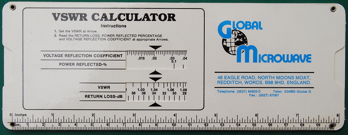
Global Microwave VSWR Calculator made by Datalizer Slide Charts. This is essentially the same as the M/A.COM example above.
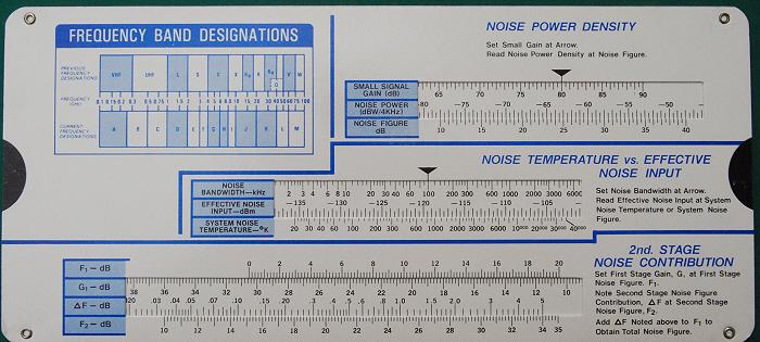
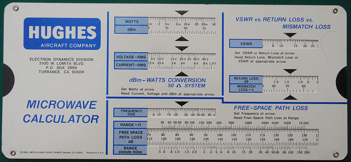
Hughes Aircraft Compnay Microwave Calculator made by Arth-
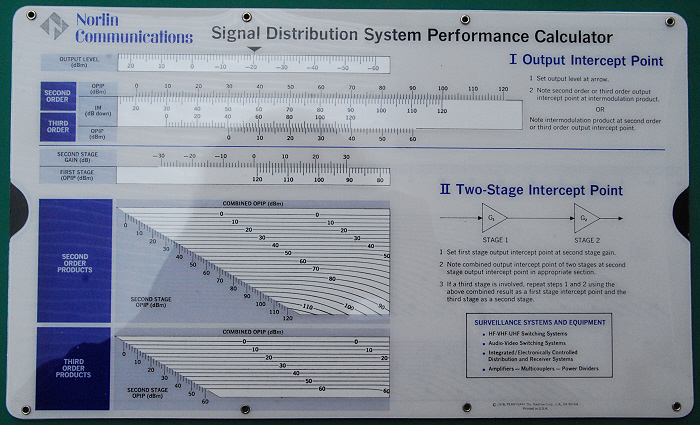
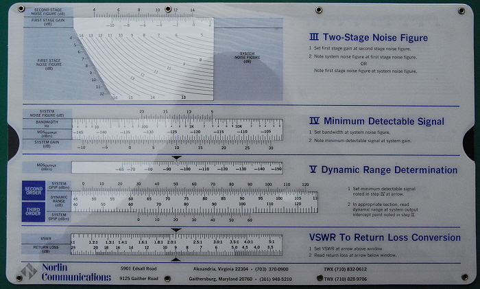
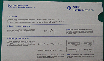
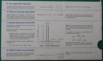
Nortin Communictions Signal Distribution System Performance Calculator made by Perrygraf
©1978. The large plastic calculator is housed in a paper sleeve (the bottom two pictures).
It says “The Nortin Signal Distribution System Performance Calculator provides a
convenient means of determining dynamic range performance of wideband multi-
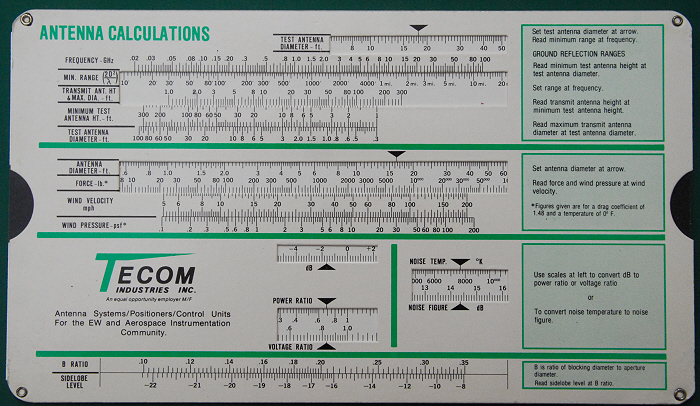
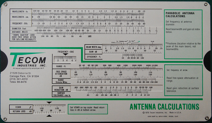
Tecom Industries Inc Antenna Calculations slide chart made by Arth-
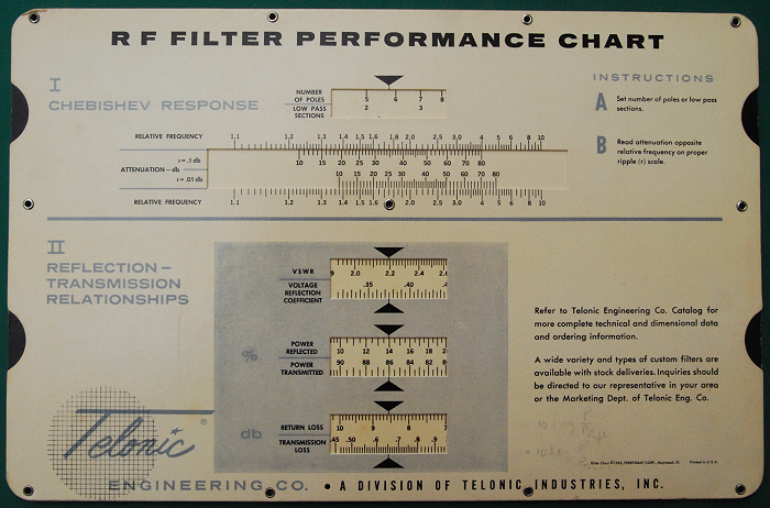
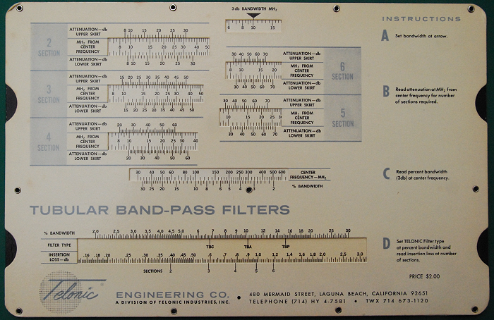
Telonic Engineering Co RF Filter Performance Chart made byPerrygraf ©1965. Its construction
is slightly unusual as it has two slides (upper & lower). On the upper face section
I calculates the Chebishev response. The Chebishev filter has a very steep roll-
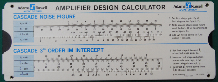
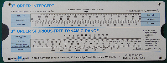
Adams Russell Amplifier Design Calculator made by Perrygraf ©1978. Using the principle
of Intercept the 3rd order spurious-
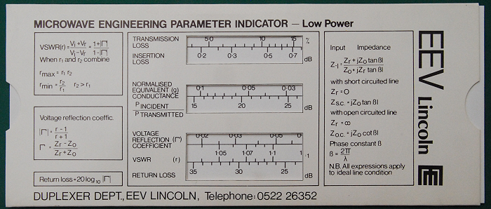
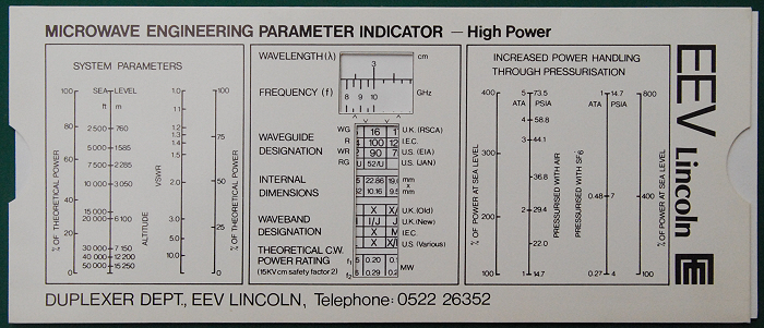
EEV Lincoln Microwave Engineering Parameter Indicator. The upper face is Low Power and the lower face High Power. Whilst information given includes various formulae that the calculator is based on there are no instructions on its use. However the high power side is for specific waveguide types and gives dimensions and theoretical CW power rating as well as wavelength and frequency.
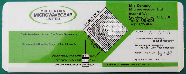
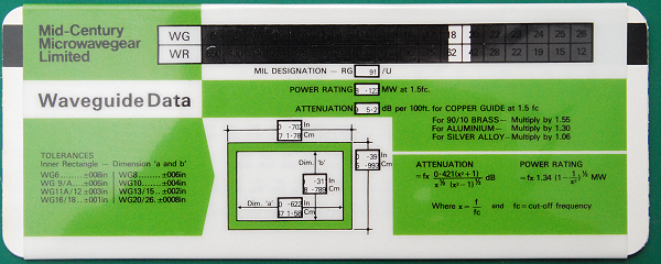
Mid-

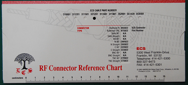
ECS Low-
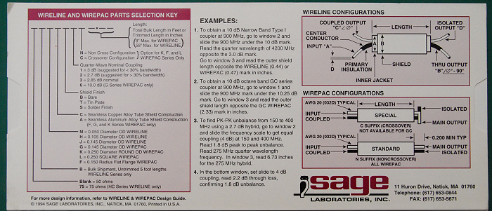
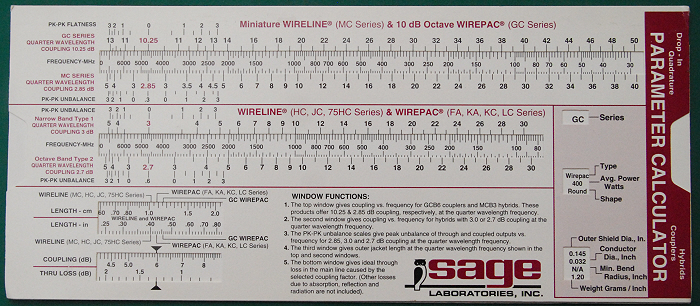
Sage Laboratories Inc Wireline and Wirepac Selection Key and Parameter Calculator ©1994 made by Datalizer Slide Charts. The upper side gives examples of how to use the chart to select the appropriate coupler using the slide and windows on the lower side.
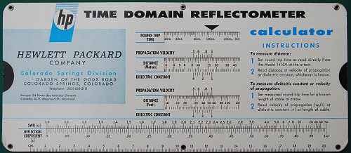
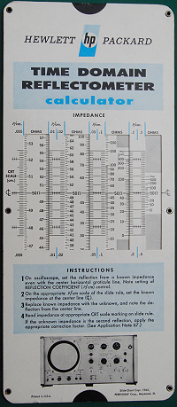
Hewlett Packard Time Domain Reflectometer Calculator made by Perrygraf dated 1965. Intended for use with the Model 1415A Reflectometer, it could be used to calculate the distance from the round trip time given the propagation velocity or dielectric constant, or to find either of these from the round trip time in a known length of cable. The second side gives the instructions for finding an unknown impedance by reference to a known one using the oscilloscope and the calculator.
| Early Sets |
| Traditional Sets |
| Later Sets |
| Major Makers |
| Instruments |
| Miscellanea |
| W F Stanley |
| A G Thornton |
| W H Harling |
| Elliott Bros |
| J Halden |
| Riefler |
| E O Richter |
| Kern, Aarau |
| Keuffel & Esser |
| Compasses |
| Pocket compasses |
| Beam compasses |
| Dividers |
| Proportional dividers |
| Pens |
| Pencils |
| Rules |
| Protractors |
| Squares |
| Parallels |
| Pantographs |
| Sectors |
| Planimeters |
| Map Measurers |
| Miscellaneous |
| Materials Used |
| Who made them |
| Who made these |
| Addiator |
| Addimult |
| Other German |
| USA |
| Miscellaneous |
| Microscopes |
| Barometers |
| Hydrometers & Scales |
| Pedometers |
| Surveying Instruments |
| Other instruments |
| Workshop Measuring Tools |
| Catalogues & Brochures |
| Micrometers & Verniers |
| Engineering rules and gauges |
| Wood rules & calipers |
| Dial gauges & miscellaneous |